How to Select the Right Motor Shaft for Industrial Equipment
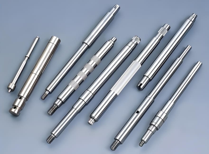
Selecting a motor for industrial equipment involves more than matching voltage, power, and speed. The mechanical interface must also connect correctly to the driven machine and withstand the forces created during operation. A shaft that does not match the application can lead to installation difficulties, excessive vibration, premature bearing wear, or failure of the drive assembly.
The Motor Shaft should therefore be selected as part of the complete motor-and-load system. Engineers and equipment buyers need to consider the connected component, torque requirements, mounting arrangement, environment, and service conditions. A structured assessment can prevent costly mismatches and make replacement decisions more reliable.
Begin With the Driven Equipment
The first question is what the motor must drive. Pumps, fans, conveyors, gearboxes, mixers, and machine tools impose different mechanical loads. Some require a direct coupling, while others use belts, pulleys, gears, sprockets, or specialized connections.
Identify how the driven component attaches to the shaft and whether it applies radial, axial, or overhung loads. A belt pulley, for example, can create substantial radial force because of belt tension. A coupling may impose different demands, particularly if alignment is imperfect.
The motor manufacturer’s allowable shaft loads should be checked against these requirements. A motor should not be selected solely because its rated power appears adequate.
Establish Torque and Speed Requirements
Torque and rotational speed determine the basic power-transmission demand. The shaft must carry the required torque without excessive stress or deformation. However, the operating profile is just as important as the nominal value.
Consider start-up torque, acceleration time, reversing, braking, shock, and the frequency of operating cycles. A machine that starts under a heavy load may create a greater shaft demand than one that starts unloaded. Variable-speed drives can also change the dynamic conditions experienced by the rotating assembly.
Where loads fluctuate, engineers should evaluate peak and cyclic stresses rather than using only average operating values.
Choose the Correct Shaft Geometry
Shaft diameter and extension length must suit the connected component and available installation space. A longer extension may be necessary to accommodate a coupling or pulley, but additional length can increase bending deflection when external forces are applied.
Connection features should be confirmed before purchase. These may include a keyway, spline, thread, flat, cross-hole, taper, or special shoulder. The dimensions and positions of these features must match the mating part.
A nominally identical diameter does not guarantee compatibility. Keyway depth, thread pitch, usable shaft length, tolerance, and shoulder position can all determine whether assembly is possible.
Consider the Material and Environment
Most industrial motor shafts are manufactured from steel grades selected for strength, toughness, and machinability. The required grade depends on motor size, duty, and load. Corrosive, humid, washdown, or high-temperature environments may require a different material or protective treatment.
Consider exposure to chemicals, salt, abrasive dust, and cleaning agents. Surface protection should be appropriate for the environment and should not interfere with bearing fits or coupling interfaces.
Where wear is concentrated at a specific surface, a suitable hardening process may be useful. Such treatments should be specified according to the actual contact conditions.
Check Accuracy and Dynamic Performance
Runout, straightness, concentricity, and surface finish influence how the shaft operates with bearings and connected components. Excessive runout can produce vibration, while poor bearing-seat dimensions can affect fit and clearance.
For high-speed applications, balancing requirements should be reviewed. The shaft and attached rotating components may need to be assessed together because a pulley, coupling, or fan changes the assembly’s mass distribution.
Review Installation and Maintenance Needs
A shaft may be technically suitable but difficult to install if access is restricted or the connection requires special tools. Consider whether the attached component needs frequent removal, whether a locking device is required, and how alignment will be verified.
Replacement planning should include the exact motor model, shaft drawing, and connection specification. Photographs and approximate measurements can help with identification, but they should not replace dimensional verification for critical equipment.
Create a Practical Selection Checklist
Before approving a shaft, confirm the required torque and speed, radial and axial loads, mounting position, connection geometry, material, environmental exposure, tolerances, and maintenance expectations. Ask the supplier for dimensional drawings and relevant material or inspection information where needed.
Conclusion
Selecting the right motor shaft means matching its mechanical characteristics to the complete industrial application. Load analysis, geometry, connection details, material, precision, and installation requirements all contribute to a successful choice. A systematic selection process helps equipment owners avoid incompatible parts, reduce mechanical stress, and maintain dependable machine operation.